The entire transmission device of the cycloid reducer can be divided into three parts: the input part, the deceleration part, and the output part. A double eccentric sleeve with a displacement of 180° is installed on the input shaft, and two eccentric sleeves are installed on the eccentric sleeve. The roller bearing forms the H mechanism. The center holes of the two cycloidal wheels are the raceways of the eccentric sleeve bearing on the pivoting arm. The cycloidal wheel meshes with a set of circularly arranged needle teeth on the needle gear to form the teeth. The internal meshing reduction mechanism with a difference of one tooth is generally in order to reduce friction. In a reducer with a small reduction speed ratio, the needle tooth is also equipped with a needle tooth sleeve. When using the cycloid reducer, you need to pay attention to the following little knowledge:
1. When the cycloid reducer is connected with the gear and sprocket, the parallelism of the axis of the two must be ensured.
2. When a coupling is used to connect the cycloid reducer with the matching machinery, an elastic coupling is recommended.
3. When the cycloid reducer is connected with the matching mechanical coupling, the coaxiality of the axis of the two should not exceed the allowable range of the coupling.
4. If it is necessary to adopt other special installation forms other than foot-plate horizontal installation and flange-type vertical installation, corresponding lubrication and sealing measures must be taken to ensure sufficient lubrication of the reducer to prevent oil leakage.
5. In the occasion of high impact, vibration or frequent starting, the base and the foundation need to be fixed with positioning pins (self-prepared) in addition to the foot bolts for connection.
6. When connecting couplings, gears, sprockets and other couplings to the output shaft of the cycloid reducer, direct hammering must not be used. The bolts should be screwed in through the screw holes at the shaft extension and pressed in through the pressure plate.
7. When the cycloid reducer is installed, it can be adjusted by using pads. The height of the pads does not exceed three pieces, and can also be adjusted with wedge iron, but the cycloid reducer must be replaced with flat pads after calibration.

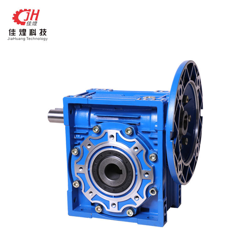
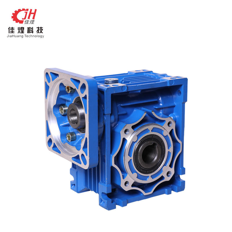
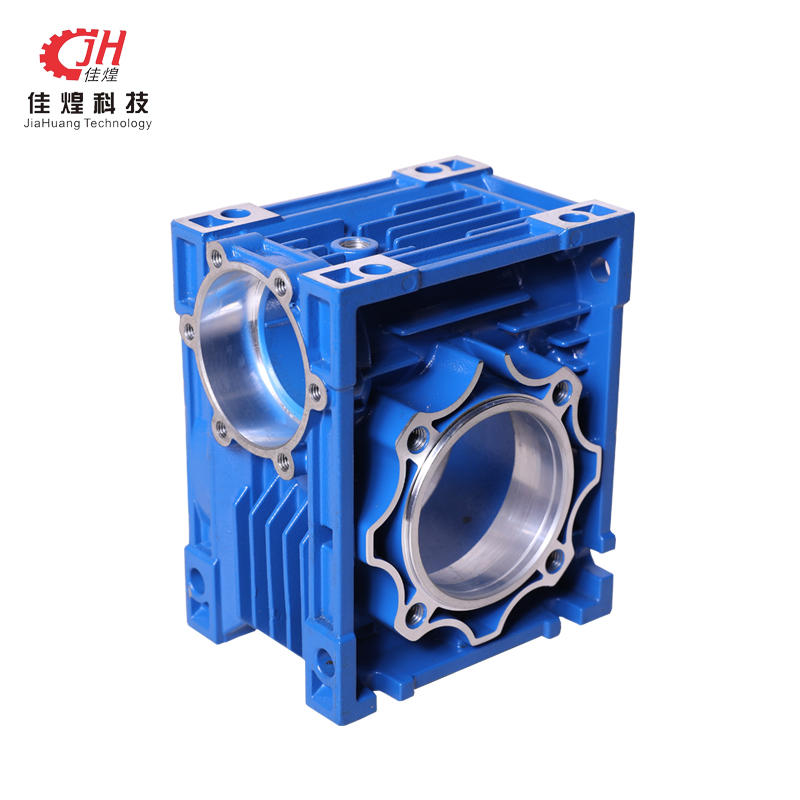
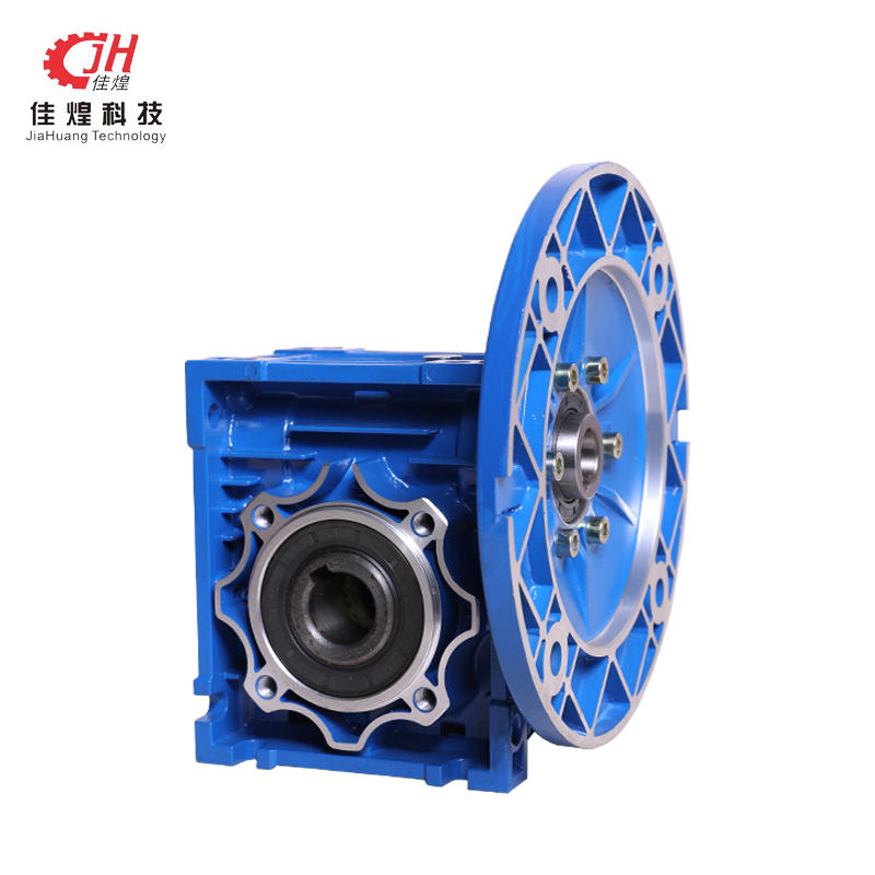
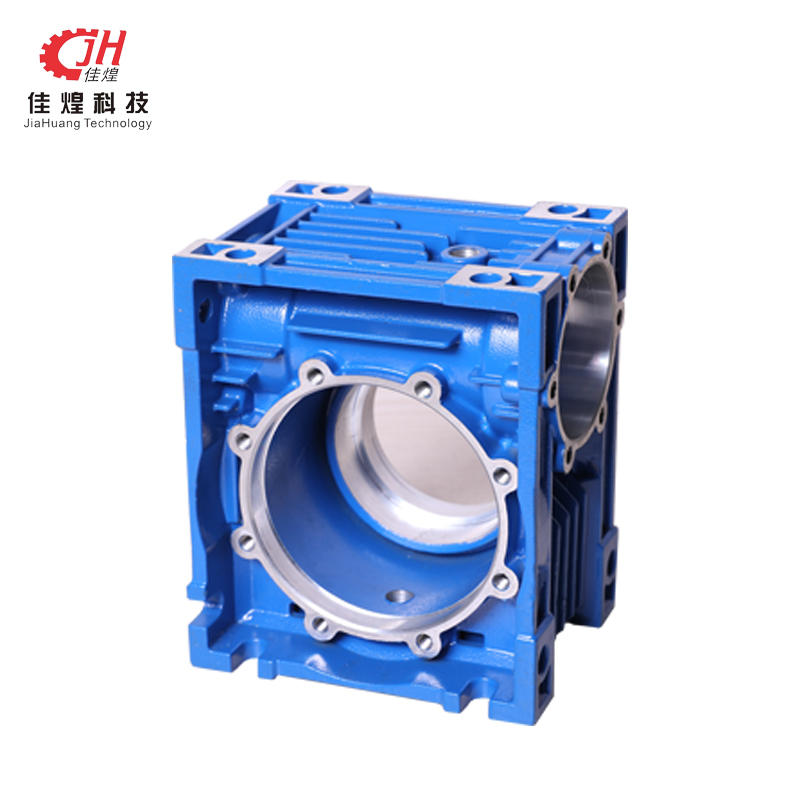
Product name:NMRV Method Worm Gear Blue Reducer Co...
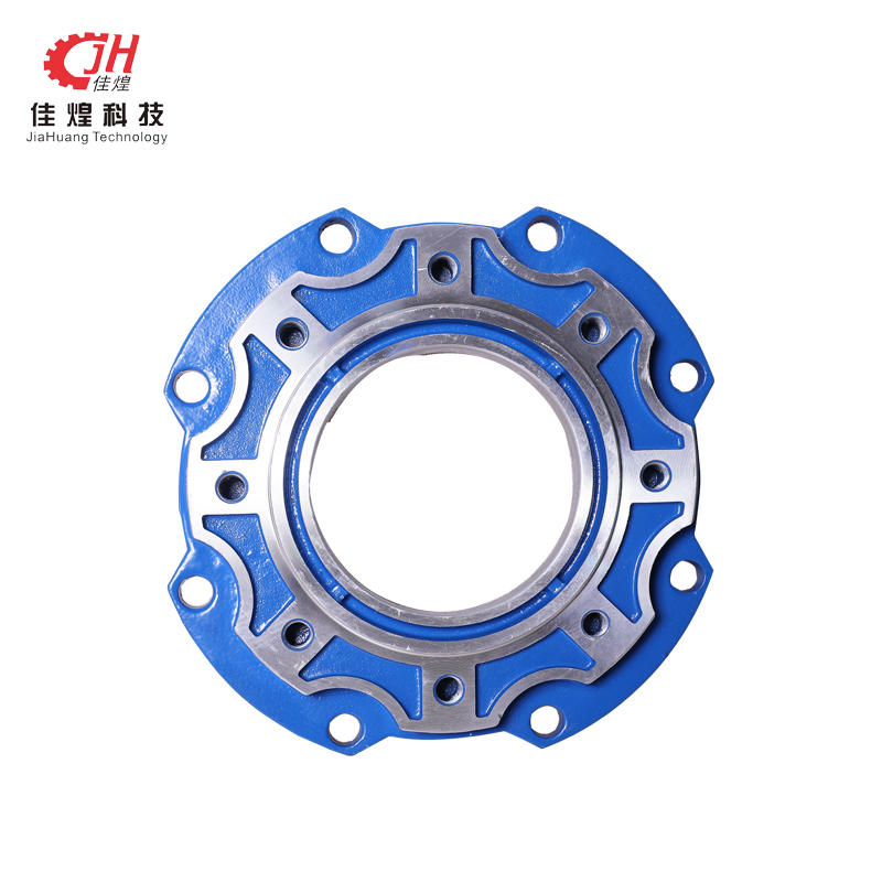
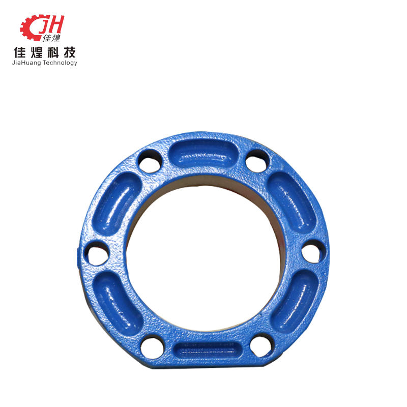
NMRV round flange machine-installation precautions...
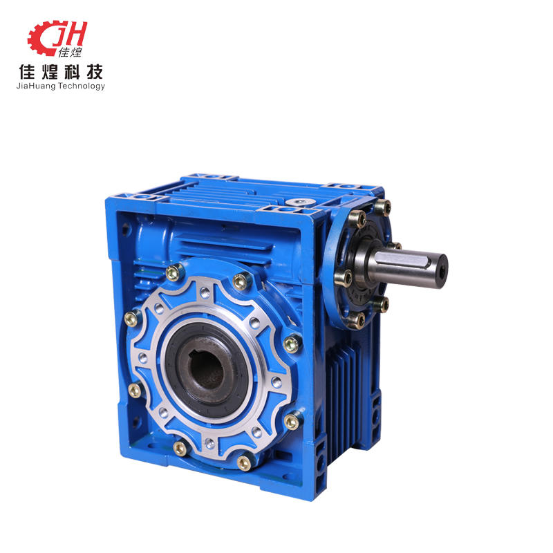
Advantage performance: 1.Compact structure, light ...
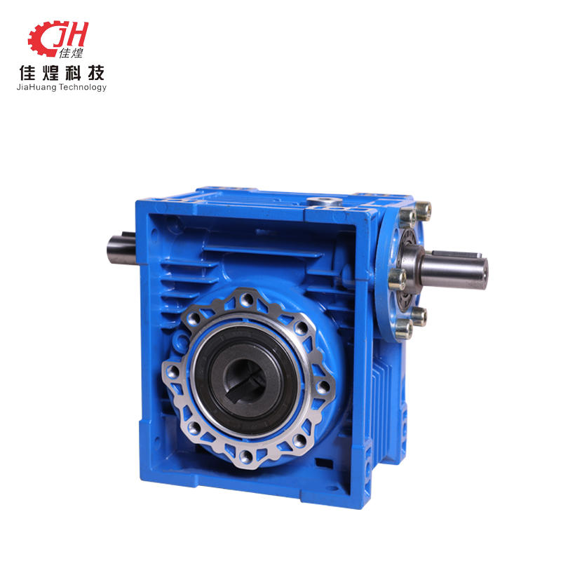

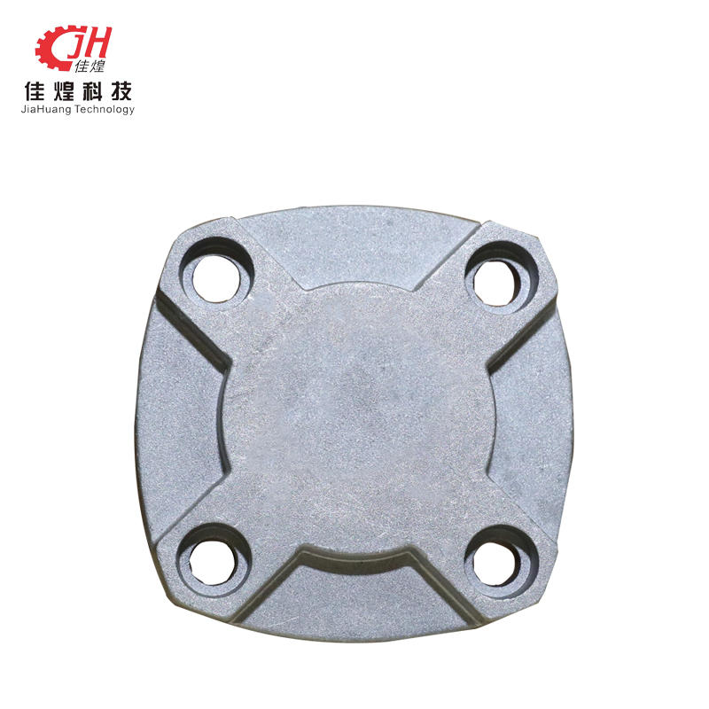
Product Name:Speed Reducer Die Cast Housing Type:S...
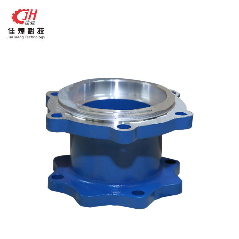
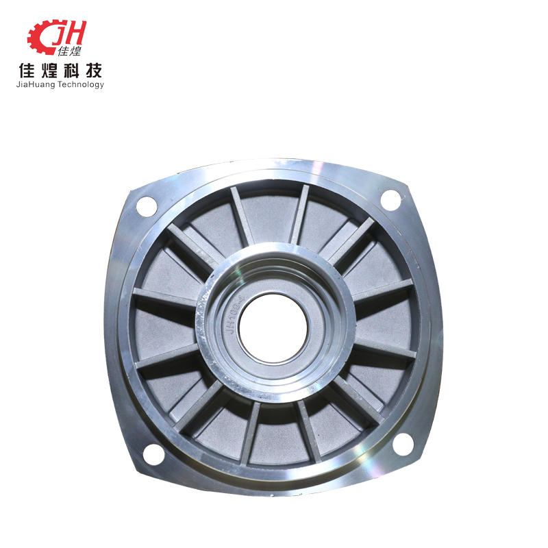
Product Name: Name:Adaptor Flange Colour:Many colo...
+86-15268125268
+86-0571-82163928
address:
JIAHUANG TRANSMISSION TECHNOLOGY CO., LTD., BAILANG VILLAGE, YIPENG STREET, XIAOSHAN DISTRICT, HANGZHOU, ZHEJIANG, CHINA
E-mail:
[email protected]
Phone:+86-15268125268
Fax:+86-0571-82163928
Copyright © Hangzhou Jiahuang Transmission Technology Co., Ltd. Rights Reserved. Privacy
